
The development of new Tokamak concepts based on a very high magnetic field gives rise to the possibility of a new generation of compact systems and creates the opportunity to approach a family of fusion systems beyond the state of the art and thereby initiate the transition from huge machines to smaller systems compatible with concepts such as distributed generation, with less impact on the environment.
In the development of fusion systems, in addition to the conceptual evolution of elements towards new options, such as the “liquid blanket” for example, it is necessary to introduce new materials and new technologies for the construction of suitable magnets to obtain sufficiently intense magnetic fields, since low-temperature superconducting (LTS) materials are not valid for operating at the 20T [1] level required for the new designs. The quality of cables based on LTS superconducting materials is very high, as are the coils based on them [2], but LTS materials are one of the limiting factors in achieving the field values required for the new generations of compact reactors with lower cost and lower impact.
The development of so-called high-temperature superconductors (HTS) has made it possible to make magnets up to 45.5 T [3], while LTS wires cannot reach the superconducting state at fields above 19 T. The development of wiring for magnetic coils with HTS wires is now a strategic player in the fusion race, and new players have joined the race. At least two private companies (Commonwealth Fusion Systems and Tokamak Energy) plan to build the first compact power plant by 2035. Compact fusion power plants are expected to deliver 0.5 GW in a modular configuration that allows for flexible territorial distribution.
New designs require new tools. HTS-based cables and coils need a specific calculation environment with regard to their properties and performance from a mechanical, thermal or electromagnetic point of view.
Within the FusionCAT project, collaboration between BSC and ICMAB has started to build a new computational module for the ALYA platform [4] that allows the possibility to tackle the multi-physical problems that the design of coils for Fusion applications must face. In a first stage, the development of an electromagnetic module that allows the 2D and 3D calculation of the current density distribution in the HTS cable according to its specific architecture and working conditions has been tackled. The problems related to the magnetisation of the HTS conductor by external field and by the electric current itself have been solved and tested with existing and published benchmarking results [5] as well as with solutions obtained by the ICMAB group using COMSOL.
In this context of collaboration, BSC has developed the Magnet module on the experimental basis carried out by ICMAB with emphasis on including the appropriate resources to solve the problems presented by HTS in the design of the windings required by the magnets of a Tokamak. The module contemplates the capacity to include mechanical and thermal aspects, already existing in the ALYA environment, giving rise to a very useful multiphysics tool. The project includes the design of physical tests to validate the calculation. The use of Hall Magnetometry and loss analysis performed by ICMAB constitute the key pieces in the verification of results. In parallel to BSC, the less complex problems are solved using COMSOL to contrast the results with those obtained by the Magnet module.
The Magnet module for HTS simulations
In this first stage, the HTS module has been developed to solve the H formulation, for low frequency, of the Faraday equation (Eq. 1), and assuming that HTS materials behave according to the non-linear equation (Eq. 3).
?0 ∂H/∂t + rot(? J)=0 (Eq. 1)
J = rot(H) (Eq. 2)
?=Ec/Jc (J/Jc)n-1 (Eq. 3)
This formulation speaks directly in terms of the essential quantities involved in typical superconducting engineering problems: magnetic field (H) and electric current density (J). It also includes the physical properties of the material involved such as Jc (critical current) and “n”, values both measured and supplied by the manufacturer. Ec marks the electric field achieved when J=Jc. The value of Ec=10-4 V/m is conventionally accepted. Although Eq. 1 allows the electromagnetic problem to be solved, the condition div(H)=0 could occasionally be included explicitly using a Lagrange multiplier to avoid the possible incompatibility of an overdetermined system.
HTS tape modelling
Conductors for stranding and making high-temperature critical superconducting cables are commercially available as tapes between 30 and 100 microns thick and between 2 and 12 mm wide. In these tapes, only a 1-3 micron layer corresponds to the textured HTS ceramic, with its crystalline structure oriented along the entire length of the tape (Fig. 1).
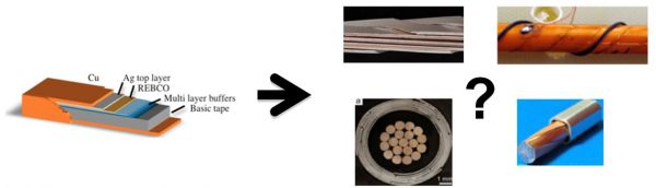
This ribbon architecture introduces a difficulty in calculating the actual current density values in this layer. The large scale difference between the HTS layer and the full size of the ribbons leads to so-called “homogenisation”. This simplification means that the current can flow through the entire thickness of the tape, and the value of Jc is the full critical current (Ic) divided by the tape section area. The effect of this assumption can only be seen at the scale of the thickness, but not when considering the coil as a whole, at a much larger scale. In case of a local event, such as a hot spot, the analysis performed on the tape thickness scale makes sense to consider the internal architecture of the superconducting conductor.
HTS tape characterization
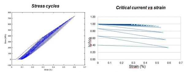
The values of Jc and “n” are essential for the modelling of HTS systems, with Jc being the most critical. However, in the case of Jc, this value has a large impact on the behaviour of the HTS material, values of Jc= 2× 10⁸ A/ m2 are typical in the homogenised domain, which is common in HTS engineering. This parameter is not a constant, it depends on the temperature (T), the magnetic field (H) and also on the deformation (ε) due to the mechanical conditions in which the superconductor works. In addition, the direction (α) of the external magnetic field in which the superconductor operates, in relation to the orientation of the crystalline HTS ceramic also modifies the value of Jc due to the lattice anisotropy of the HTS crystals.
Manufacturers provide the values of Jc as a function of B,T and α, whose dependence on mechanical strain is provided indirectly as the maximum critical stress, which is the mechanical stress at which Jc decreases by 5 %. Measurements of this dependence are performed by some Research Laboratories. Currently, ICMAB can perform this characterisation under magnetic field up to 9T at temperatures up to 5K. It is currently building a new facility to reach 16T, bringing its capacity closer to the levels needed for the study of accelerators and compact Tokamaks.
Results Validation
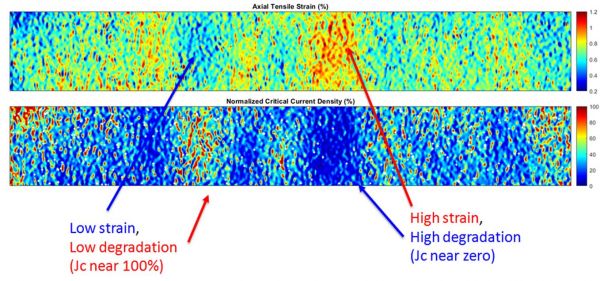
The application of an external magnetic field on an element with zero resistance leads to a perfect shielding of the field, the system does not allow the field to penetrate into its volume. HTS materials (Type II) have a limit to the current density, the critical current density, which allows the field to enter but, when the applied field is removed, the field inside the HTS material remains partially, only what is known as the trapped field.
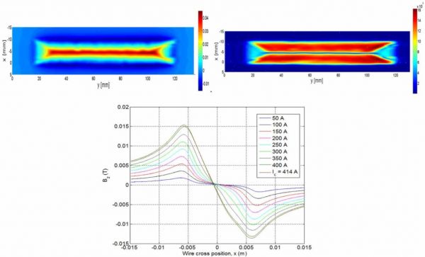
This trapped field corresponds to the persistent currents induced into the material, the critical current density field. The distribution in the field presents the local values of the critical current. The measurement of the perpendicular component of the trapped field can be performed on the surface of the tape after it has been subjected, until saturation, to an external magnetic field using a Hall probe sweeping the surface [6]. The magnetic field map obtained allows the calculation of the local value of the critical current. This distribution allows comparison with results obtained through modelling or to obtain the values needed for modelling. This procedure can be performed on tapes through which current is flowing in order to determine how it is distributed (Fig.4).
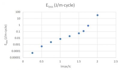
Magnetic characterisation by scanning Hall microscopy is sufficiently powerful to compare the experimental results with those of the simulation with the Maxwell module developed by BSC. In the second stage, we are developing complementary mechanisms for large-scale experimental validation of the HTS system. Among the most relevant values in a superconductor-based system is the value of the power loss. It is a critical value for the design. The power losses in a superconductor are due to the energy invested in the formation of the internal magnetic field of the superconductor during the charging and discharging processes. In the regime of changing magnetic field, an electric field E is produced due to the flux variation. The scalar product J.E is a power density and its integral spread over the whole volume of the superconductor is the energy loss per unit time during the switching cycle.
Modelling allows the calculation of losses and their measurement allows experimental validation of the calculation. Their sizing can be carried out in two ways. A thermal pathway, which measures the heat emitted in the cryogenic system, and an electrical pathway, which measures the real component of the impedance. Both measurement systems are under development at ICMAB. The validation process of the new ALYA module is concerned, in comparison with existing solutions, both in solving the problem in a reduced dimension using COMSOL and in contrasting its solution with significant experimental values. Figure 5 shows the losses per metre and cycle of a 12 mm wide belt when carrying an alternating current of 50Hz and 100-800 A, Ic=400A. The calculation of losses in a loop or a non-cylindrical coil (3D problem) is within the scope of the ALYA options.
References:
[1] Limites NbTi y Nb3Sn, y Desarrollo de W&R Bi–2212 High Field Acelerator Magnets A. Godeke, D. Cheng, D. R. Dietderich, P. Ferracin, S. O. Prestemon, G. Sabbi, y R. M. Scanlan. eScholarship Open Access Publications from the University of California (2008)
[2] A review de comercial high temperatura superconducting materiales para large magnets: from wires and tapes to cables and conductors. D Uglietti; Superconductor Science and Technology, Volume 32, Number 5, April 2020
[3] 45.5-tesla direct-current magnetic field generated with high-temperature superconducting magnet. Seungyong Hahn, Kwanglok Kim; Nature volume 570, pages 496–499 (2019)
[5] HTS numerical modelling workinggroup— www.HTSmodelling.com Benchmarking
[6] “Magnetic mapping, a way to test and understand current flows in thin and bulk superconductors”. Granados X, Iliescu S, Bozzo B, Bartolome E, Puig T, Obradors X, Amoros J, Carrera M. https://doi.org/10.4028/www.scientific.net/AST.47.1
Source : FusionCAT news
The FusionCAT project (001-P-001722) has been 50% co-financed with € 1.960.963,66 by the European Fund for Regional Development of the European Union within the framework of the 2014-2020 ERDF Operational Program of Catalonia, with the support of the Generalitat of Catalonia.
![]()
![]()
![]()
1 thought on “HPC tool development for the design of HTS superconducting components for tokamak fusion systems”